介紹
直流電機
直流電機將直流電形式的電能轉換為電機軸旋轉運動形式的機械能。
直流電機的速度可以通過施加不同的直流電壓來控制;而電機的旋轉方向可以通過反轉通過它的電流方向來改變。
為了施加變化的電壓,我們可以利用 PWM 技術。為了反轉電流,我們可以使用 H 橋電路或採用 H 橋技術的電機驅動器 IC。
有關直流電機及其使用方法、H 橋電路配置和 PWM 技術的更多信息,請參閱傳感器和模塊部分中的直流電機主題。
基於 NodeMCU 的 ESP8266 可用於控制直流電機的速度和旋轉方向。NodeMCU 在其 GPIO 引腳上具有 PWM 功能,我們可以使用它來控制直流電機。
要了解 NodeMCU PWM,請參閱 帶有 Arduino IDE的 NodeMCU PWM或帶有 ESPlorer IDE 的 NodeMCU PWM。
接口圖
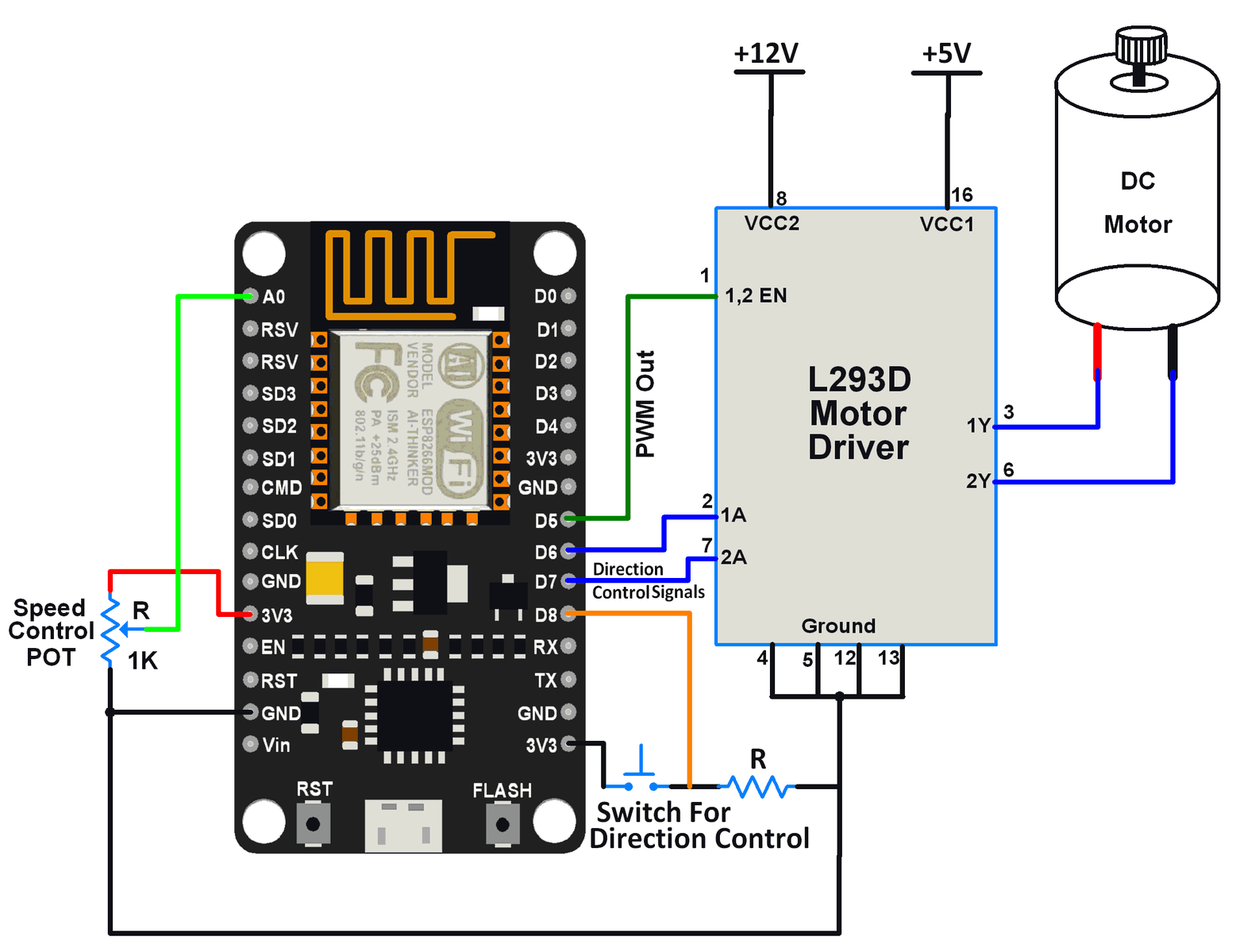
NodeMCU 通過 L293D 驅動器與直流電機接口
例子
讓我們使用 NodeMCU 套件控制直流電機的速度和旋轉方向。
在這裡,電位器用作速度控制的手段,而來自觸覺開關的輸入用於改變電機的方向。
我們可以利用 NodeMCU 的 ADC 功能來讀取電位器。我們可以利用 NodeMCU 的 GPIO 中斷功能來讀取開關狀態。
要了解 NodeMCU ADC,請參閱 帶有 Arduino IDE的 NodeMCU ADC或帶有 ESPlorer IDE 的 NodeMCU ADC。
要了解 NodeMCU GPIO 中斷,請參閱 使用 Arduino IDE的 NodeMCU GPIO 中斷或使用 ESPlorer IDE 的 NodeMCU GPIO 中斷。
L293D電機驅動IC用於控制電機的方向。NodeMCU 上產生的 PWM 波通過 L293D 為電機提供可變電壓。
我們可以使用 ESPlorer IDE(帶有 Lua 腳本)以及使用 Arduino IDE(帶有 Arduino 草圖)向 NodeMCU 編寫程序
要了解更多關於如何使用 ESPlorer IDE 開始使用 NodeMCU,請參閱 使用 ESPlorer IDE 開始使用 NodeMCU。有關如何開始使用帶有 Arduino IDE 的 NodeMCU 的更多信息,請參閱 使用 Arduino IDE 開始使用 NodeMCU。
直流電機的 Lua 腳本
PWM_Pin = 5        --set pins for control
DirectionPin1 = 6
DirectionPin2 = 7
DirectionControlPin = 8

timer_id = 1
delay_ms = 200

PWMfrequency = 1000 -- Set PWM frequency
PWMDutyCycle = 512  -- Set PWM duty cycle in between 0-1023

pwm.setup(PWM_Pin, PWMfrequency, PWMDutyCycle)-- Setup PWM
pwm.start(PWM_Pin)   -- Start PWM on PWM pin

gpio.mode(DirectionPin1,gpio.OUTPUT)--set direction control pins as output pins
gpio.mode(DirectionPin2,gpio.OUTPUT)
gpio.mode(DirectionControlPin,gpio.INT,gpio.PULLUP)-- Set GPIO interrupt mode for pin

DirectionPinValue1 = gpio.LOW   -- write direction control pin initial states
DirectionPinValue2 = gpio.HIGH
gpio.write(DirectionPin1,DirectionPinValue1)
gpio.write(DirectionPin2,DirectionPinValue2)

function interrupt(level, stamp)-- callback function while interrupt
    gpio.trig(DirectionControlPin) -- disable interrupt for that pin

    if (DirectionPinValue1 == gpio.HIGH) then
        DirectionPinValue1 = gpio.LOW
        gpio.write(DirectionPin1,DirectionPinValue1)
    else
        DirectionPinValue1 = gpio.HIGH
        gpio.write(DirectionPin1,DirectionPinValue1)
    end
    if (DirectionPinValue2 == gpio.HIGH) then
        DirectionPinValue2 = gpio.LOW
        gpio.write(DirectionPin2,DirectionPinValue2)
    else
        DirectionPinValue2 = gpio.HIGH
        gpio.write(DirectionPin2,DirectionPinValue2)
    end

    tmr.delay(700000)    -- wait 700 ms
    print('Rotational Direction changed..!')--print direction change msg

    gpio.trig(DirectionControlPin,"high",interrupt)--re-enable interrupt on pin while exit
end

gpio.trig(DirectionControlPin,"high",interrupt)-- set interrupt type high i.e. High level

function POT_Control()
    POT_read = adc.read(0) -- Read pot using ADC
    if POT_read> 1023 then-- Limit PWM to max of duty cycle
    POT_read = 1023
    end
    pwm.setduty(PWM_Pin, POT_read)-- set PWM duty cycle to DC motor
    print('Speed (%):',math.floor(100*POT_read/1023))-- print speed of DC motor
end

tmr.alarm(timer_id,delay_ms,tmr.ALARM_AUTO,function() POT_Control() end)--start alarm function to PWM duty cycle control
直流電機的 Arduino 草圖
bool d1 = HIGH;
bool d2 = LOW;

void motor_direction(){
 d1 = !d1;
 d2 = !d2;
 for(inti = 0; i<10000; i++)
  for(int j =0; j<10000; j++);
}

void setup() {
 Serial.begin(9600);
 pinMode(D5, OUTPUT);  /* PWM pin for Speed Control */
 pinMode(D6, OUTPUT);  /* Motor control pin 1 */
 pinMode(D7, OUTPUT);  /* Motor control pin 2 */
 pinMode(D8, INPUT_PULLUP);  /* Interrupt pin for direction control */
 attachInterrupt(D8, motor_direction, HIGH);
 /* call motor direction function on HIGH level at pin 8 */
}

void loop() {
 intpwm_adc;
 pwm_adc = analogRead(A0); /* Input from Potentiometer for speed control */
 digitalWrite(D6,d1);
 digitalWrite(D7,d2);
 analogWrite(D5,pwm_adc);
 delay(100);
}
資料來源:https://www.electronicwings.com/nodemcu/dc-motor-interfacing-with-nodemcu
沒有留言:
張貼留言