介紹

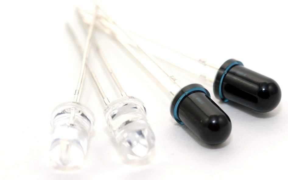
紅外 LED 和光電二極管
IR 通信利用電磁波譜中的 IR(紅外)波。我們的眼睛看不到紅外波,這使得它對無線通信很有用。
IR LED 用於以數字形式無線傳輸數據(0 – LED 關閉或 1 – LED 開啟)。
IR 光電二極管或 IR 光電晶體管接收此數據。IR 接收器(IR 光電二極管或 IR 光電晶體管)根據光的強度給出不同的電流值。
可以調製傳輸的數據,並且有特殊的解碼器 IR 接收器(如 TSOP1738)可以接收調製數據。
有關 IR 通信的更多信息,請參閱傳感器和模塊部分中的主題 IR 通信 。
NodeMCU 可以利用 IR 通信從啟用 IR 的遙控器讀取命令,通過 IR 介質發送數據等。
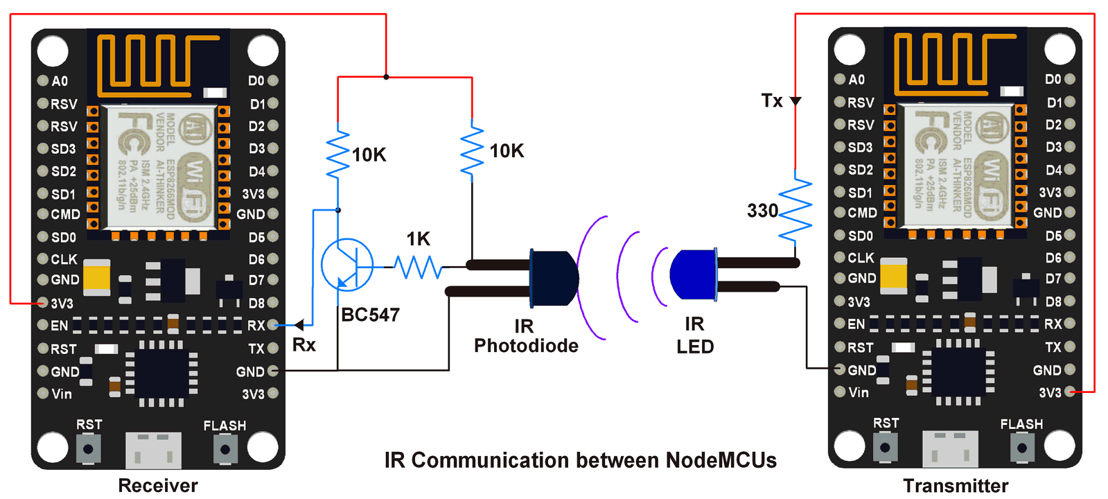
接口圖

NodeMCU 之間的 IR 通信
注意: 在上圖中,對於 IR LED,較長的引線是陽極,較短的引線是陰極。
注意:由於 NodeMCU Tx Rx 引腳用於將腳本上傳到電路板,因此在將腳本上傳/保存到 ESP 時斷開 Tx Rx 與 IR 電路的連接。將腳本成功上傳/保存到 NodeMCU 後連接它。
例子
讓我們為兩個 NodeMCU 之間的 IR 通信編寫 Lua 腳本。一個將被配置為發射器,另一個被配置為接收器。
要了解如何開始使用 NodeMCU 的 Lua 腳本,請參閱 使用 ESPlorer IDE 開始使用 NodeMCU
請注意,我們為此通信使用 1200 波特率。
用於 IR 通信的 Lua 腳本
發射器端用於 IR 的 Lua 腳本
count = 0

-- set uart0 with 1200 baud rate, 8 databits, no pariy, 1 stop bit with echo
uart.setup(0,1200,8,0,1,1)

while true do   -- continuous send count
    print(count)
    count = count + 1
tmr.delay(1000000)
end
接收端用於 IR 的 Lua 腳本
-- set uart0 with 1200 baud rate, 8 databits, no pariy, 1 stop bit with echo
uart.setup(0,1200,8,0,1,1)
--print received data
uart.on("data", "\n", function(data) print("receive from uart:", data) end, 0)
要了解基於 Lua 的 NodeMCU UART 功能,請參閱 NodeMCU UART with ESPlorer IDE。
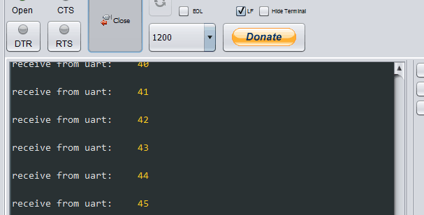
下面是接收端NodeMCU的ESPlorer串行監視器輸出窗口

此外,我們可以為 NodeMCU 編寫 IR 通信的 Arduino Sketch。要了解如何開始使用適用於 NodeMCU 的 Arduino 草圖,請參閱 使用 Arduino IDE 開始使用 NodeMCU
用於紅外通信的 Arduino Sketch
發射器端用於 IR 的 Arduino Sketch
void setup() {
 Serial.begin(1200);  /* Define baud rate for serial communication */
}

void loop() {
 int count;
 for(count = 0; count<100; count++){
  Serial.println(count);
  delay(1000);
 }
}
接收端用於 IR 的 Arduino Sketch
void setup() {
 Serial.begin(1200);  /* Define baud rate for serial communication */
}

void loop() {
 if(Serial.available())  /* If data is available on serial port */
  {
    Serial.print(char(Serial.read()));  /* Print character received on to the serial monitor */
  }
}
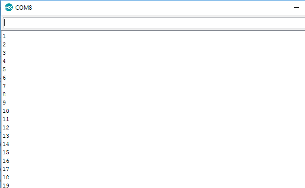
下面是接收端 NodeMCU 的 Arduino 串行監視器輸出窗口

資料來源:https://www.electronicwings.com/nodemcu/ir-communication-using-nodemcu
沒有留言:
張貼留言